Better built with Building Information Modeling
5 years, 2 months ago
By Craig Neises | Carl A. Nelson & Company
Over the past dozen years, Building Information Modeling, or BIM, has represented an evolutionary advance in building design and construction coordination compared to earlier methods. The money- and time-saving benefits the technology offers to construction clients, meanwhile, can only be described as revolutionary.
From the design through the construction of a project, BIM coordination holds the promise of reduced cost, faster construction and better quality overall.
“The value of seeing the facility, including all modeled components, visually before, during and after construction is outstanding,” said Jamie Stanley, Vice President of Operations in Carl A. Nelson & Company’s office in Cedar Falls, Iowa.
BIM is a tool for embedding important project data directly into the planning documents — something not possible within the finite dimensions of a sheet of blueprint paper, or offered in CAD software. Building Information Modeling puts the details of every system or component at designers’ and builders’ fingertips, from floor plans and specifications right down to the positioning of doorstops. Because in the acronym, the key letter is the middle one.
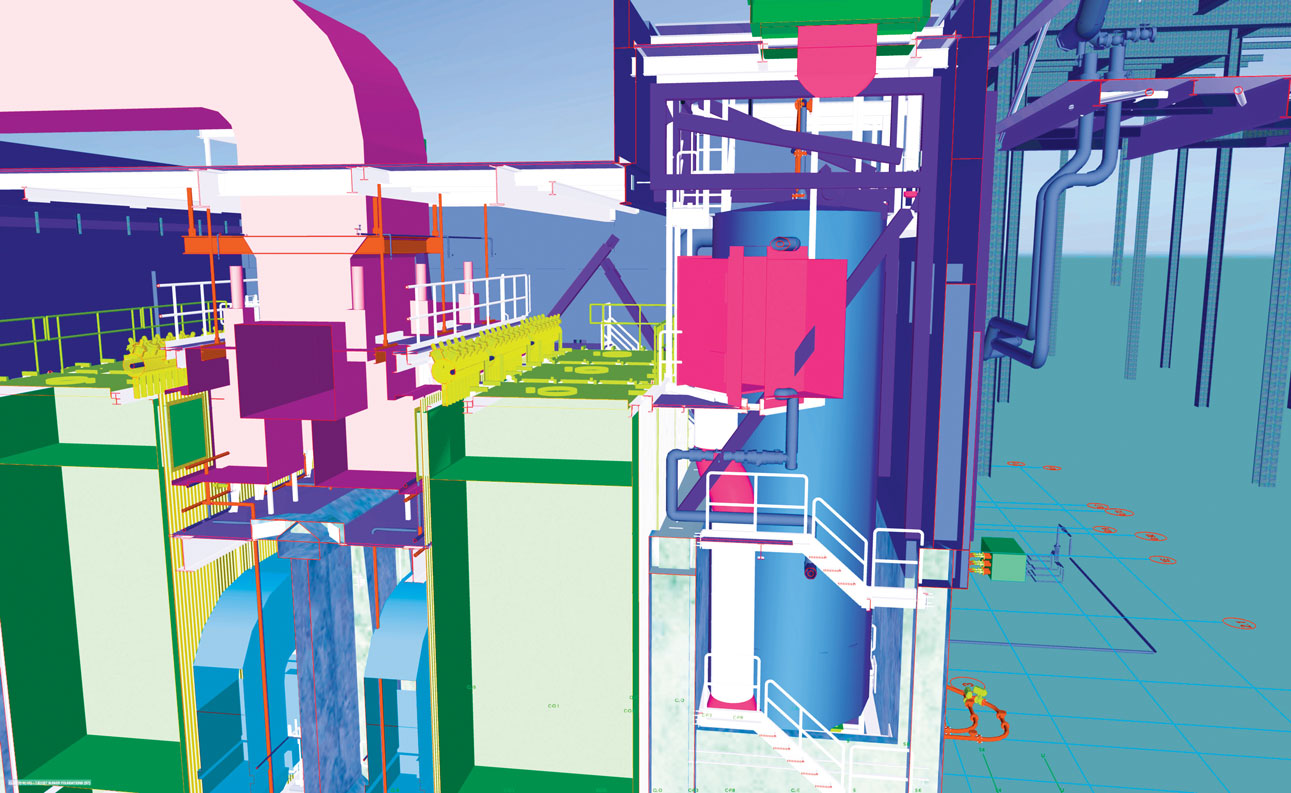
The last letter is what empowers builders and designers to see all that information brought together in a 3D environment to visualize a finished project and to detect and resolve constructability issues before they are discovered in the field.
Every BIM model starts with the basic dimensions of a space drawn in software. On a remodeling project, field measurements and as-built drawings provide the information needed to create a model. For new construction, a model frequently begins with the basic design from the architectural firm, then with components layered in from MEPT consultants, which some subcontractors have the capability of creating during pre-construction or adjusting based on conditions in the field.
• NELSON DESIGN, INC., CAN BRING BUILDING INFORMATION MODELING AND MORE TO YOUR NEXT PROJECT. CLICK HERE TO LEARN MORE.
Changes made digitally to the plans can be made available immediately to builders.
“Architects and engineers design in 3D and are able to combine the models of multiple disciplines in their model,” said Nelson Design, Inc., architect Ellen McCulley, AIA, LEED AP, NCARB. “They obviously are able to resolve a lot of problems at this stage. Once the subs create shop drawings and take MEPT design to a higher level of detail, they are able to identify and then resolve any potential constructability issues.”
Most commonly used by Carl A. Nelson & Company (CANCO) on design-build and general contracting jobs with large pieces of equipment to be installed or complicated mechanical, electrical, plumbing and technology (MEPT) systems, BIM has become an important part of delivering successful projects to clients.
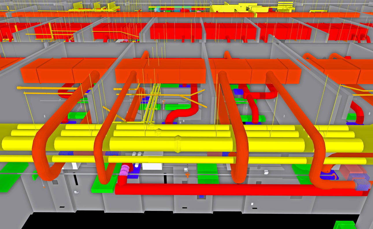
While several platforms are available today, CANCO uses Revit software from AutoDesk to develop BIM models for projects where the technology is being applied. Revit is where designs are drawn and information entered. Another software tool, Navisworks, allows models from a variety of sources, such as subcontractors, designers, suppliers and others, to be viewed in a single model, which allows better understanding of how varying components will interact. That allows for high-level coordination among project partners. The 3D review of a design using Navisworks enables designers and builders to see issues such as where ductwork and building structural elements intersect in a way that won’t work, or where plumbing pipes and data lines are trying to use the same space.
“The clash detection tool lets you filter what components you want to identify clashes amongst,” McCulley said. “For example, you could just look at clashes between the ducts or the structure. Or you could look at clashes between the ducts, plumbing and telecommunications. Or between a piece of equipment and the structure, mechanical, plumbing, electrical.
“The clash detection also allows you to create reports that can be sent out to the subcontractors so they know which areas or problems need to be addressed.”
Depending on the needs of the job, varying levels of development to BIM models are possible. For instance, a model could show the placement and dimensions of a door. At another level of detail, the model could include details like material or fire rating of the doors. The model also could allow an Owner to see how the door will look in a detailed walkthrough of a completed building with all the finishes applied.
Project Manager Ryan Harris said use of BIM on projects has grown significantly over the past 10 to 15 years, and during that time most design work moved to 3D CAD software. For project planning, he said, taking the next step to BIM isn’t difficult.
The benefits from doing so are many, Harris said.
For the Owners of a project, BIM capability in the hands of the constructor or construction manager can provide added value because of the potential for helping to ensure projects are delivered on-time and within budget by detecting issues that could affect construction before they are encountered in the field. It also helps with future maintenance and ease of use by enabling maintenance staff and end-users to see the facility in 3D before it is built, which provides the opportunity to have input on changes that will improve efficiency.
That, in turn, prevents rework and creates happier clients.
“A well-designed and coordinated project provides the most value to the facility owner,” Stanley said. “First is the time and quality of the construction that it affords. After the initial construction, a project that has been designed and spatially coordinated in 3D adds the most value for accessibility and maintenance of the facility in the future.”
• AT CARL A. NELSON & COMPANY, SAFETY IS AT THE HEART OF EVERYTHING WE DO. LEARN MORE ABOUT OUR SAFETY FOCUS.
An example is maintenance of variable air volume (VAV) boxes installed above ceilings as part of the HVAC system. Stanley said BIM documents made available to Owners “intentionally identify” requirements for accessing the boxes for testing, balancing, cleaning and future replacement. BIM also ensures lights, fire sprinkler or mechanical piping, and electrical cable trays are not installed next to or below those boxes, blocking access. The model also helps owners pinpoint the location of the VAV boxes above the ceiling.
BIM coordination is especially crucial on projects with tight spaces or an abundance of utilities.
“Anytime there’s big pieces of equipment in a small area, that’s where we’ve traditionally used it a lot to make sure everything is going to fit,” McCulley said.
BIM also speeds design development. With BIM, it no longer is necessary to produce entirely new drawings for spaces and systems affected by a change as minor as shifting a door six inches to the left. In a BIM environment, moving a door causes the change to be reflected everywhere that door exists in the model. Much more meaningful changes, such as raising an elevation, also are reflected across the model. Previously, those adjustments would have been made by hand in floor plans, elevations and sections affected by the change, and previously issued construction documents reissued.
Clash detection then allows builders to see what conflicts may result from any proposed changes.
Stanley said his first 3D BIM project was in 2008. Prior to that, 2D AutoCAD was used for design coordination, and clash detection was a manual process.
“A 3D model, and the coordination that takes place as a result of having the design done in 3D, has significantly improved quality, schedule and field changes” compared to projects not planned in 3D, Stanley said, citing the clash detection capability of Navisworks, and the ability of the various trades to make adjustments in the design prior to the start of construction, or before construction advances to a point where rework would be necessary. That allows enough design precision to be able to pre-fabricate things like fire sprinkler piping, mechanical piping, ductwork, electrical cable trays and more off-site with confidence they will fit exactly as modeled.
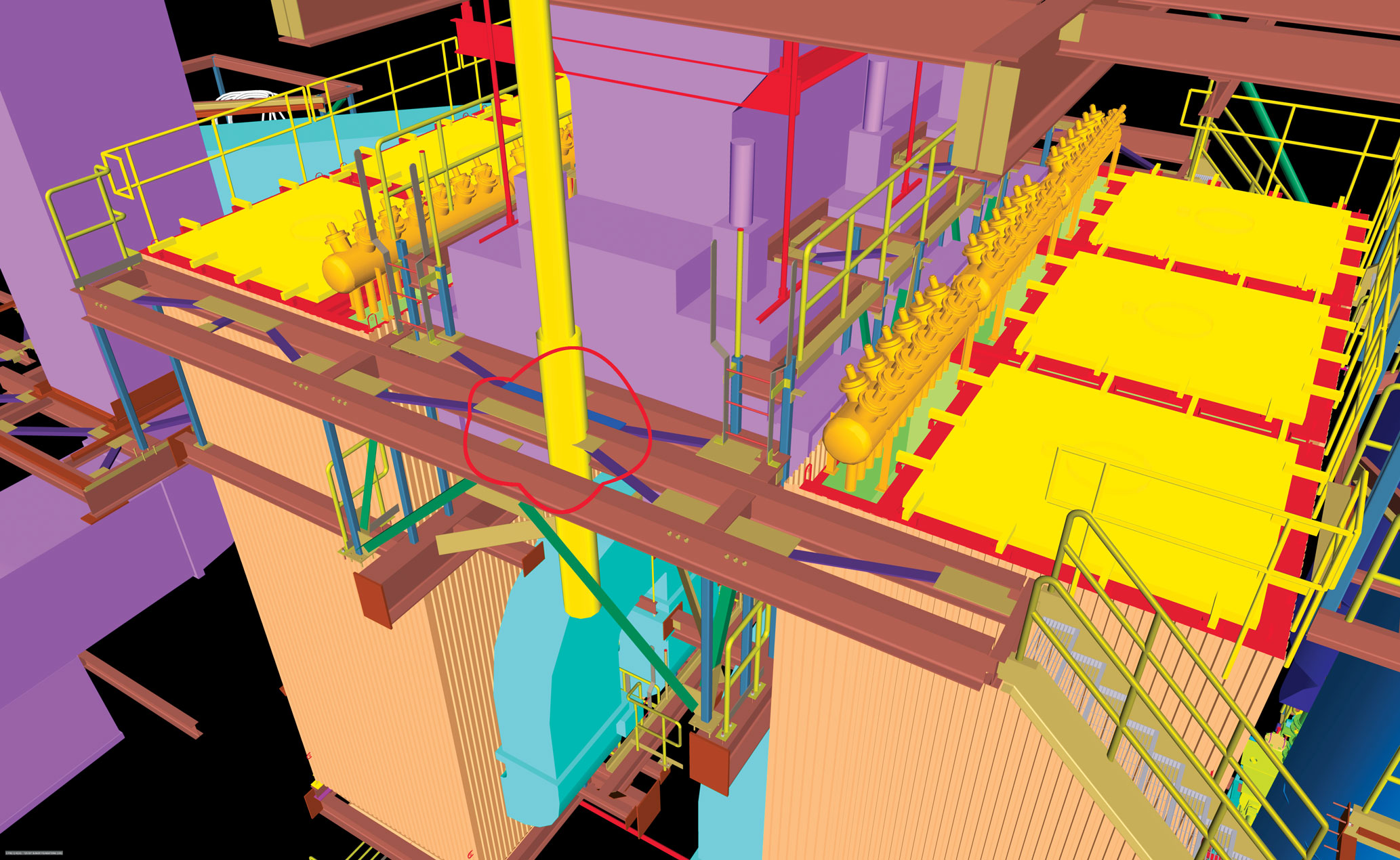
BIM applications in industrial construction
Industrial plant sites, where complex or large pieces of equipment are being removed, relocated or installed, or where complex MEPT systems factor into the project, are good candidates for BIM, McCulley said.
For example, on a $5.2 million project for an industrial client in southeast Iowa where CANCO was the general contractor, there were no detailed process pipe drawings or pipe rack supports included in the design. Stanley said the Owner accepted the added cost for 3D scans of existing piping systems and modeling as part of CANCO’s proposal to create “drawings that were accurate and usable to shop-fabricate the piping ahead of the installation, which saved time on the schedule.”
The model also eliminated changes in the field, he said. Adding BIM to the project enabled creation of 3D as-built drawings of the completed project as well.
“As this project was the first phase of a two-phase project,” Stanley said, “the Owner and their design team were able to use our models to further develop the next phase.”
Stanley added he believes that additional service contributed to the Owner awarding CANCO the contract for Phase II.
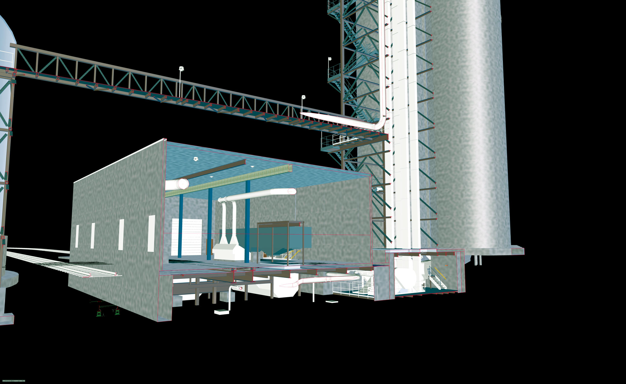
BIM modeling likewise played a vital role on a CANCO design-build project to expand a grain-handling facility in western Indiana, where a new structure was being built between existing buildings on two sides and existing pipe racks and electrical substations on another.
“We used BIM to help with site access and to show where the various cranes would be located to set the structure, as well as the process equipment,” Harris said. “We also used it to sequence and schedule steel erection and process equipment installation.”
The model enabled CANCO field personnel to proceed with erecting the structure while waiting for delivery of an evaporator. Due to the tight space, BIM helped guide a back-and-forth installation of structural steel and process equipment. An additional benefit on the project, Harris said, was identifying a conflict between the design of the structure and how some of the equipment would have to fit inside. Identified before either the steel or equipment was placed, the issue was addressed and costly rework prevented.
On a $7.9 million backup and auxiliary power project at the University of Iowa power plant in Iowa City, BIM coordination by CANCO, working as the general contractor, helped accelerate the construction schedule to meet customer demand by facilitating placement of a temporary support tower and new permanent piping supports. It also allowed offsite pre-fabrication of high-pressure steam and condensate piping prior to installation.
BIM applications in healthcare construction
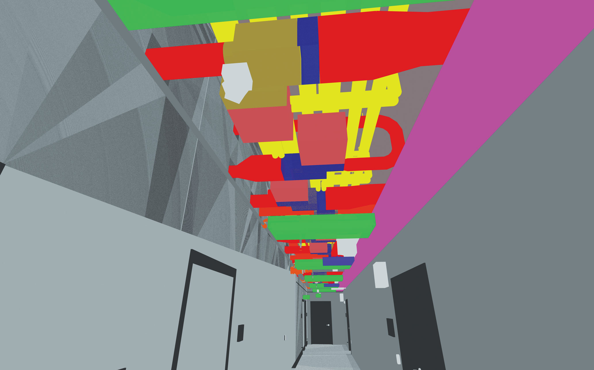
In hospitals and other complex healthcare facilities, which have the same kinds of MEPT systems as many other types of construction but with the addition of extensive piping for medical gases and often pneumatic-tube delivery systems, BIM coordination can have a significant effect on schedule and quality.
“These types of facilities oftentimes operate 24/7, so the overhead utilities are located in corridor spaces where maintenance staff can get to them without disrupting the spaces where patients are being seen and treated,” said Chris Smith, Vice President of Operations in CANCO’s Burlington office, and healthcare project executive. “The ceiling spaces in these corridors tend to be completely jam-packed with all of these utilities crammed into a small area.
“BIM modeling allows us to preplan by laying all of these utilities out ahead of time, figure out how they will best fit into the space, avoid conflicting with each other or structure, be able to be accessed for maintenance, and determine the best sequence to install.”
Examples of this benefit can be seen on a pair of highly complex medical research laboratory projects built by Carl A. Nelson & Company at the University of Iowa.
At the Pappajohn Biomedical Discovery Building on the main campus in Iowa City, CANCO was engaged as general contractor on a $15.3 million project to construct a vivarium and renovate an existing laboratory inside a sublevel of the building where head space in the ceiling was at a premium. Modeling showed multiple MEPT clashes due to the limited space.
“Some of the clashes were able to be avoided,” said Harris, who was project manager for the vivarium, “but in the end, via the BIM process, we determined there just wasn’t enough space and some ceilings had to be lowered. Had we not used BIM on this project, there would have been a lot of re-work required in the field.”
Also, Harris added, learning those issues existed at the outset of the project prevented surprises later on that would have slowed the project or added costs. The model helped, too, with scheduling the project by enabling field personnel to understand and plan the order of construction.
On another U of I project, a $24.5 million Biomedical Research Support Facility on a greenfield site on the Oakdale Campus in Coralville, Iowa, where CANCO was the design-builder, project manager Stanley cited BIM coordination of the project as a factor in meeting the university’s aggressive construction schedule.“The BIM 3D effort on this project contributed greatly to the project being substantially completed on-time,” he said.
Using the model for spatial coordination and pre-fabrication of plumbing, mechanical and electrical components allowed those components to be laid out in pipe racks and installed ahead of the interior wall construction. That reduced the time to install mechanical systems to about a month. Conventional construction would have added months to that phase of the project.
In construction, Smith said, “time is money.”
“This prefabrication saves labor in the field, which saves time on the schedule,” Smith added. “This saves contractors money, which saves clients money. Additionally, the related schedule acceleration gets the healthcare clients into their facilities quicker generating revenue from their new space.”
On the BRSF project, once the MEPT systems were in, the interior walls were built around the overhead mechanical work.
Use of the BIM model also enabled prefabrication of building components required to meet exacting tolerances for contamination prevention in the laboratory spaces. The glazed concrete masonry units used in the interior wall construction are difficult to cut in the field for electrical and mechanical wall devices, Stanley said. The BIM model of the building afforded an opportunity to laser-cut holes and pre-install service boxes for MEPT systems.
“This allowed for a clean and accurate installation of in-wall mechanical and electrical devices,” Stanley said.